
Video
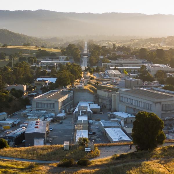
After more than a decade, LCLS was upgraded to generate even more powerful X-ray laser beams. With the LCLS-II upgrade, LCLS is around 10,000...

News Feature
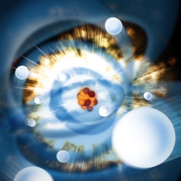
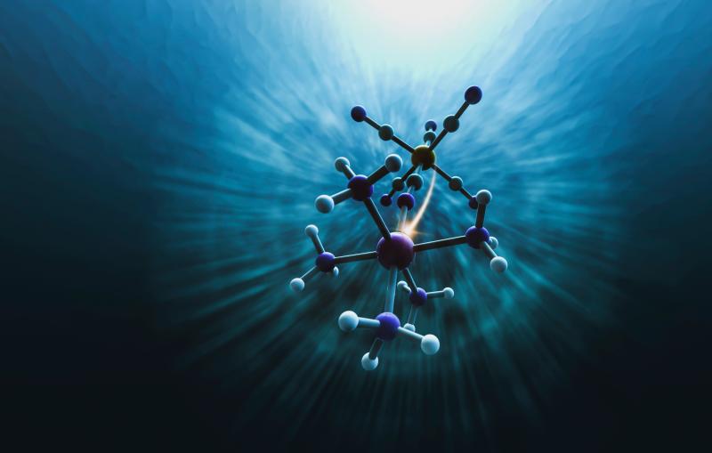
Illustration
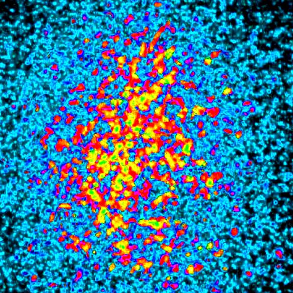
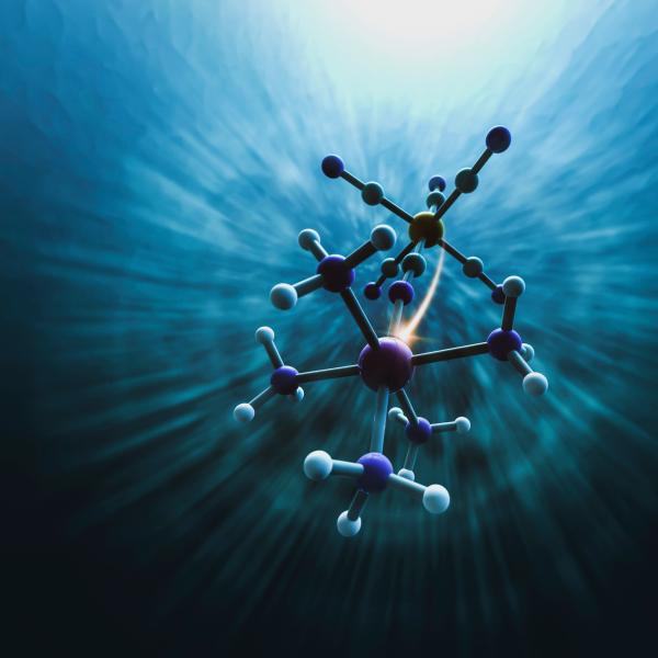
When light drives electron transfer in a molecular complex, the surrounding solvent molecules also rapidly move.
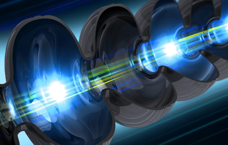
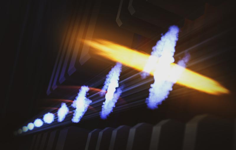
Illustration
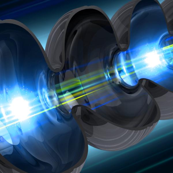
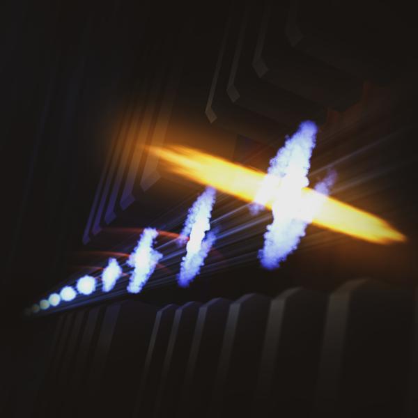
Scientists use a series of magnets to transform an electron bunch into a narrow current spike which then produces a very intense attosecond X-ray...
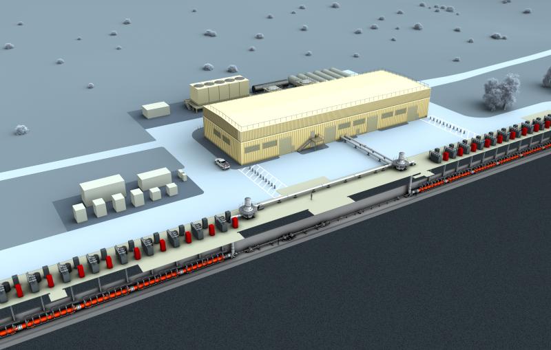
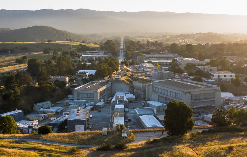
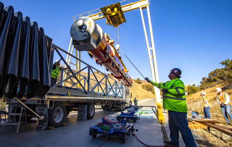
Photograph
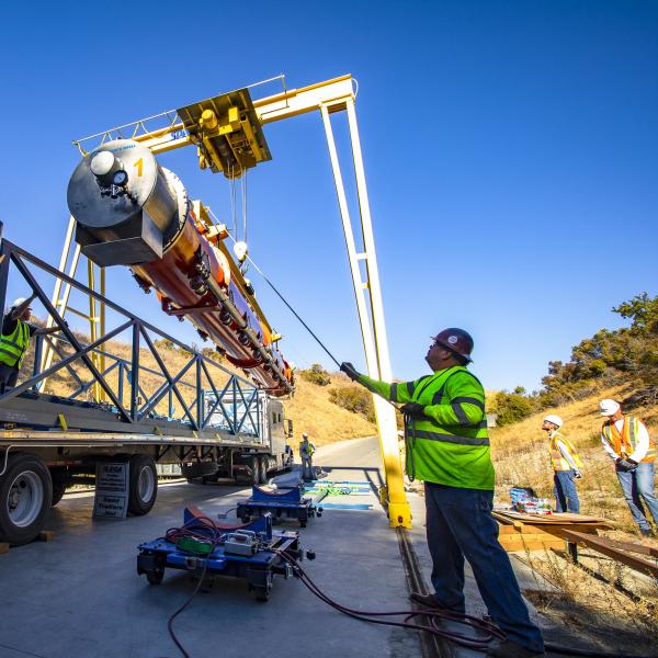
The first of 37 cryomodules for LCLS-II is moved off of its truck after being shipped from Fermilab. All the cryomodules were delivered...
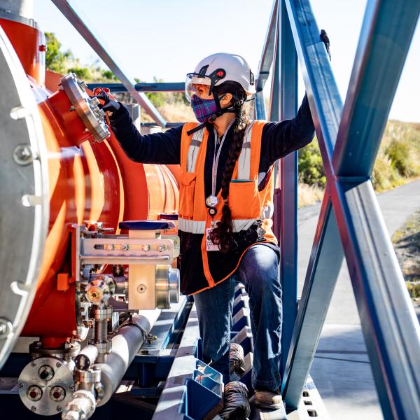
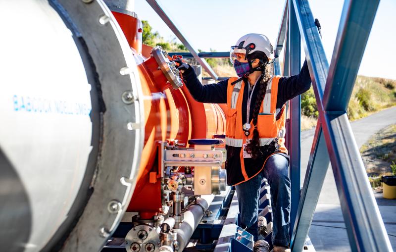
Photograph
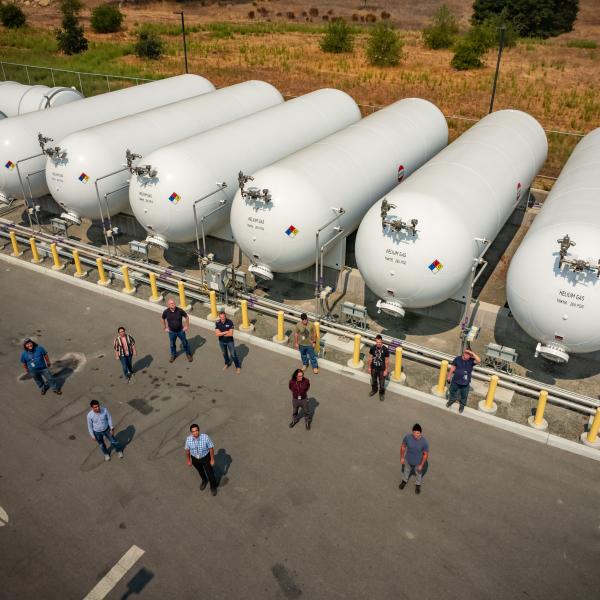
Dominique White takes a look at the last cryomodule for LCLS-II delivered from Fermi National Accelerator Laboratory.
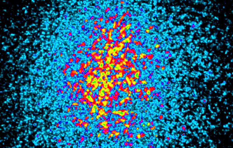
Illustration
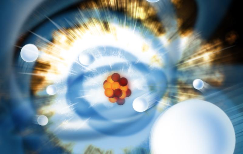
Ultra-bright X-ray laser pulses can be used to strip electrons away from atoms, creating ions with strong charges.